Relic Light-Up Pop Up Card

I made a light-up pyramid pop up card with diffraction grating diffusers, and an improved switch mechanism for #LightUpPopUpTober!
Continue reading
I made a light-up pyramid pop up card with diffraction grating diffusers, and an improved switch mechanism for #LightUpPopUpTober!
Continue reading
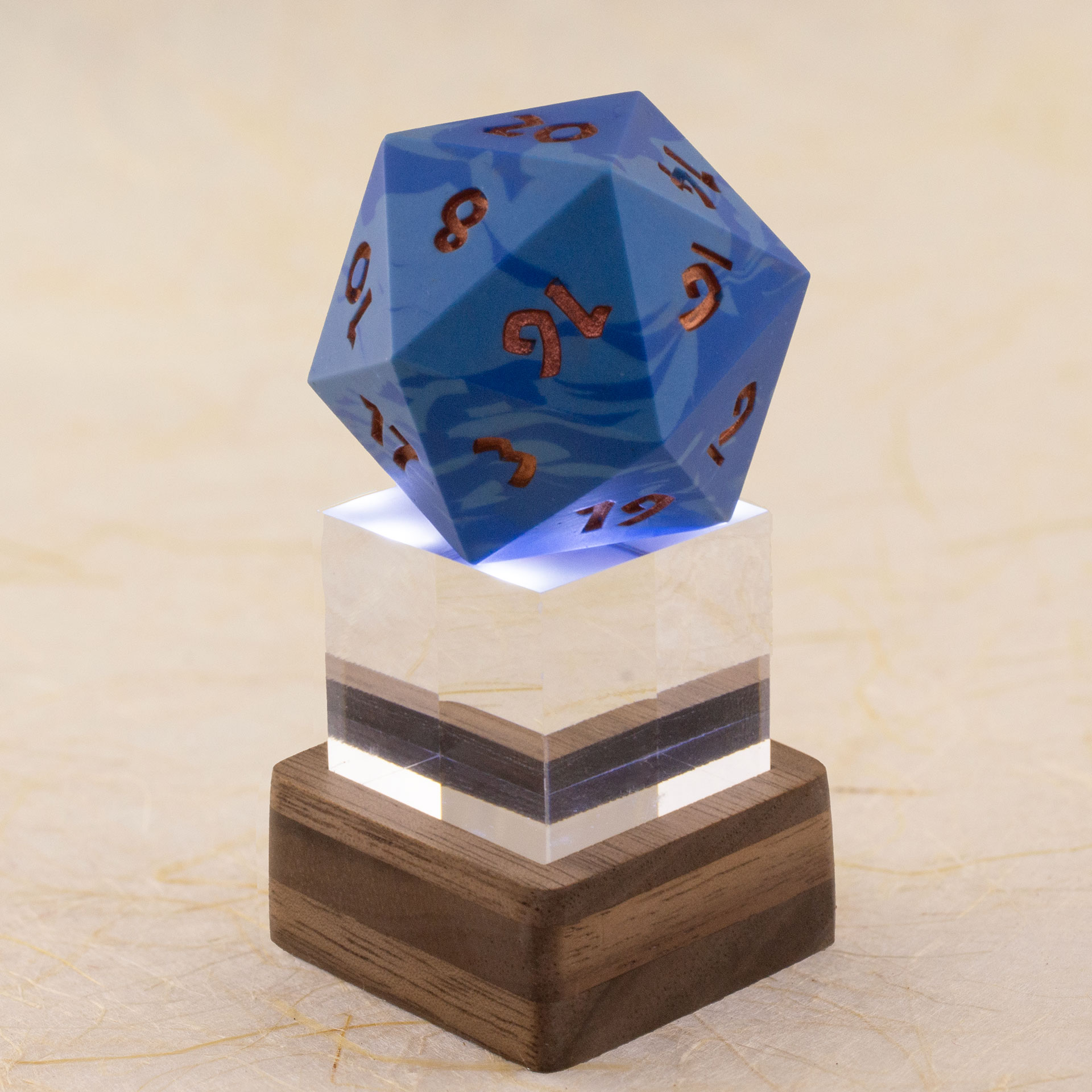
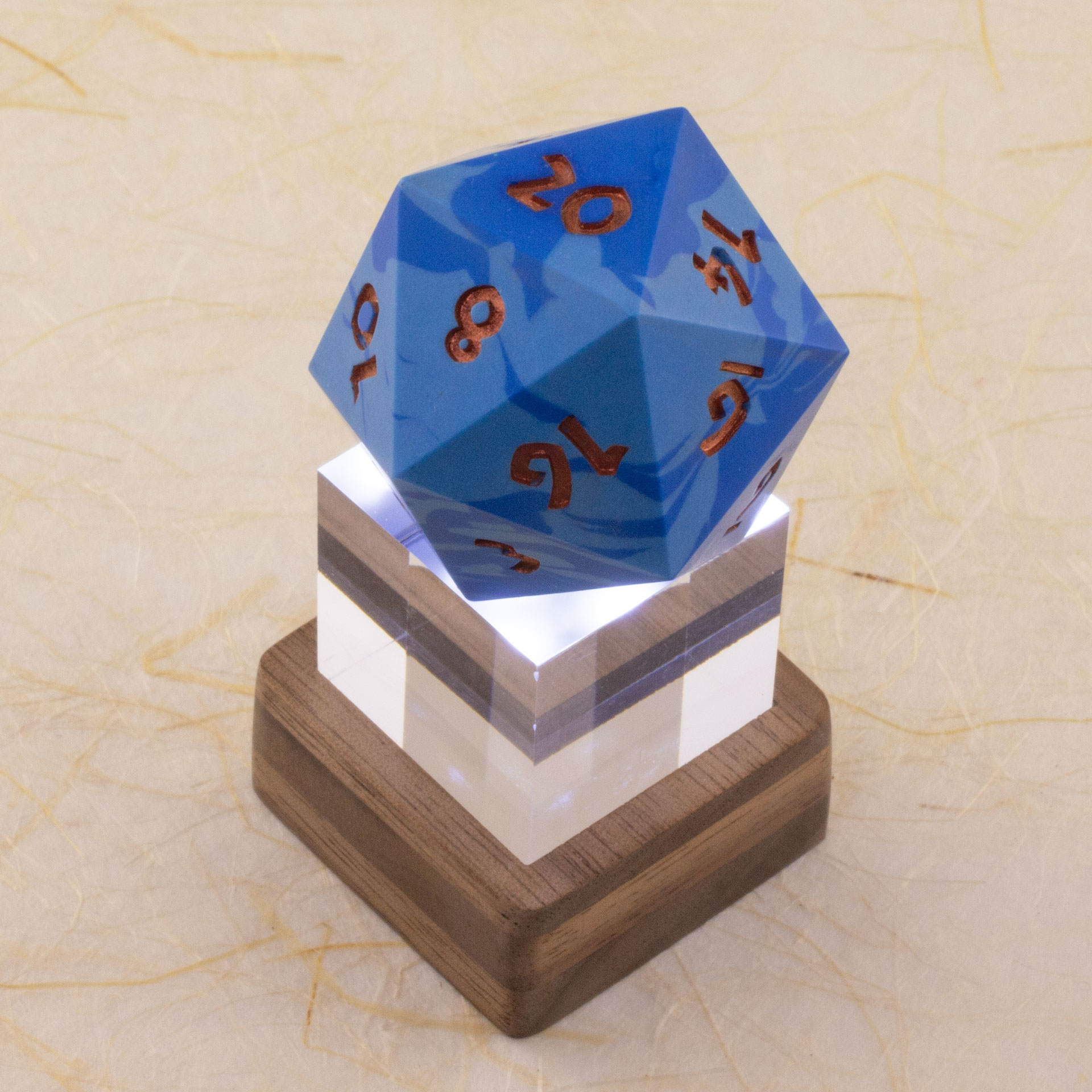
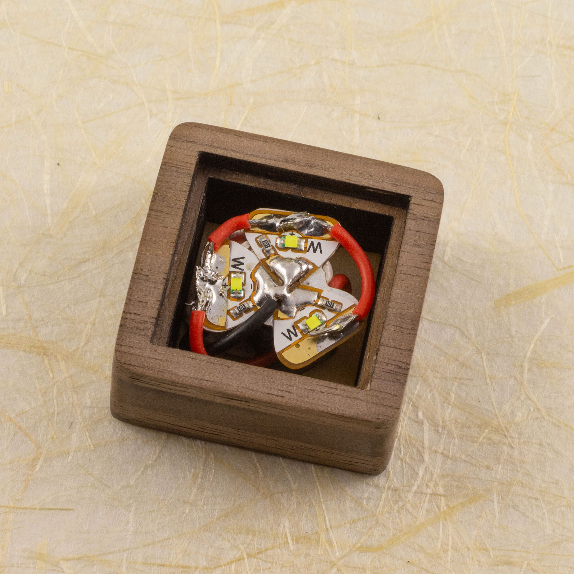
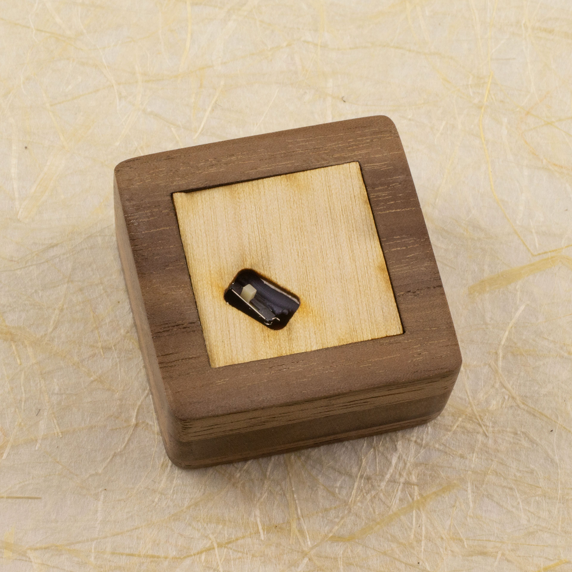
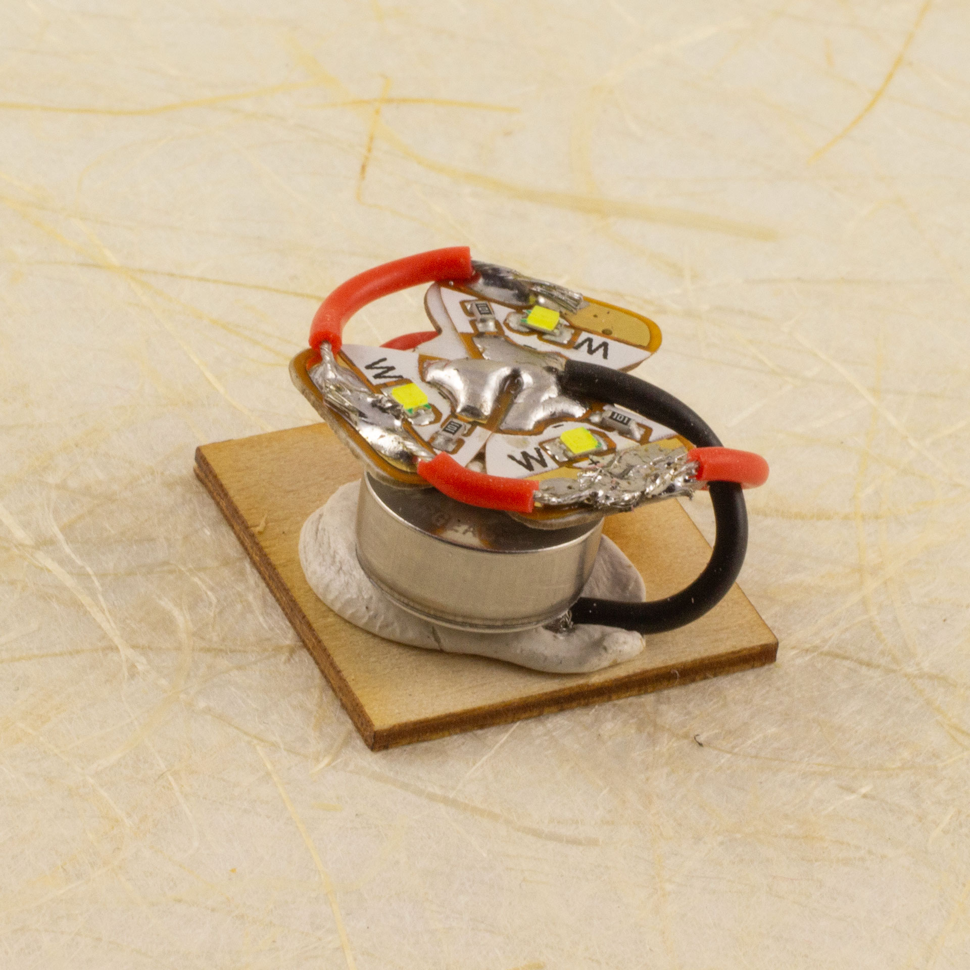
Designing and making a rechargeable light-up copper icosahedron with a 3D-printed battery holder and a magnetic panel closure.
Continue reading

I turned a Raspberry Pi I had sitting around into a network-connected USB flash drive with a custom fabricated clear acrylic case.
Continue reading
Small laser-cut polyhedra in different materials, some lit from within, inspired by paper craft.
Continue reading
A handmade laser-cut color-cycling light-up five-pointed paper star with spiral scrollwork.
Continue reading


Color-cycling Glowforge logo hexagonal panel for the 2021 Glowforge forum Regulars community project.
Continue reading
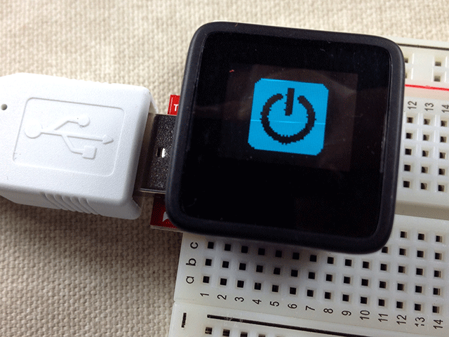
If you have been playing with the new MicroView arduino microcontroller, you likely know that it has a built-in 64 by 48 pixel OLED display and, that you can use the support library for it to control those pixels in your code. The library also supports some gauges and text output, which will likely cover most useful things people will actually want to do with the MicroView.
I, of course, immediately wanted to put various arbitrary graphics on it moments after un-boxing.
After dismissing the obvious approach of plotting individual pixels as way too much effort for play time, I came up with a way to convert bitmap images into MicroView code. I promptly splattered my company’s logo and, did a simple three-frame gear animation.
It’s easy and, you can do it, too. Here’s how:


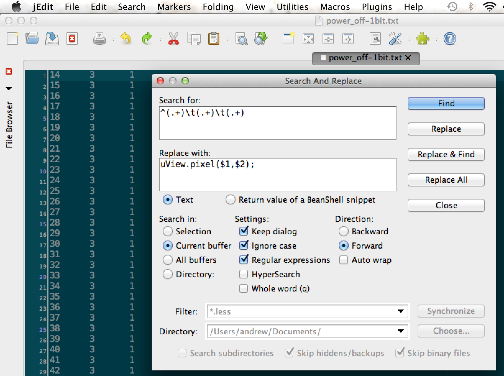
uView.pixel(x,y);A good way to do that is to run a regular expression against the file. You can do this in most decent code editors (I used jEdit). Basically, we want:
s/^(.+)\t(.+)\t.+/uView.pixel($1,$2);/g
That should give you a list of uView.pixel commands that you can paste into your code.
For reference, the code for the Power Up image is here.
The bitmaps take up a lot of memory. The gear animation uses up about half the available memory, for instance.
It should be pretty simple to write a script to optimize the images better by looking for consecutive pixels and turning them into uView.line() commands.
Old hat? Have a better way to do it? Wrote my optimization script? Let me know in the comments!